Causes and Solutions of Bearing Problem of Hammer Mill Machine
A 5000 T /d Cement production line started in April 2009, which is equipped with a limestone single-stage hammer mill machine, model PCF2022, with the maximum material particle size of 1000 mm ×1000 mm ×1500 mm, the output particle size of 70 mm (90%), and the output of 800 ton/h. The bearing, withdrawal sleeve and rotor shaft of the limestone single hammer crusher are easy to get loose, bearing brush ring; Free end (non-transmission end) bearing due to heat damage, 2 sets of bearing need to be replaced each year. Here AGICO analyzes the existing problems and introduces the treatment methods, and describes the site installation technical requirements.
Existing Problems of Hammer Mill Machine
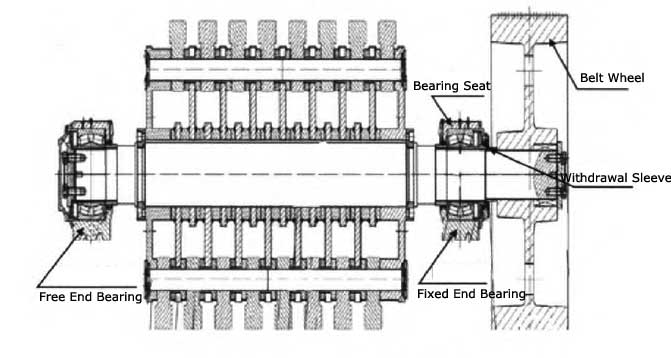
See Figure 1 for the schematic diagram of the Rotor of PCF2022 hammer mill machine. The main problems in its operation are as follows:
- The coordination between the bearing, the withdrawal sleeve and the rotor shaft becomes loose, so is the bearing brush ring.
- The temperature of the 2 sets of bearings in the crusher rotor is around 85℃ all year round, especially in summer, the bearings must be cooled by compressed air, and even need to cool down with extra cooling water on the bearing pedestal of the pulley end, in order to maintain normal production of hammer mill. Free end (non-transmission end) bearing due to heat damage, 2 sets of bearing are replaced.
Causes and Solutions of Bearing Brush Ring Looseness
Causes of Bearing Brush Ring and Looseness
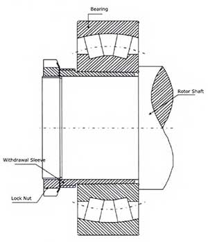
Why the bearing brush ring get loose? The reason is that the hammer mill machine field installation does not meet the technical requirements, and the insufficient bearing pretension. The rotor bearing model of the hammer crusher: 24172ECCK30J/C3 / W33, the bearing is a double row radial spherical roller bearing with tapered hole, the taper l of the inner hole is 30, with the withdrawal sleeve model: AOH24172, mounted on a cylindrical shaft (see Figure 2).
Technical Requirements for Bearing Installation
- The original clearance of the bearing shall be measured before installation. The bearing inner diameter shall be 355-400 mm, C3 series bearing original clearance of 0.40 to 0.52 mm(radial clearance); In order to rotate the outer ring several times during the measurement, it must be determined that the center line of the inner ring and the roller set overlap each other. When the original clearance is measured, the clearance is between the outer ring and the highest roller, and records are made after measurement.
- Bearing with cone hole L is usually installed in conjunction with interference. Interference can be determined by measuring the radial clearance reduction or the axial displacement of the unloader sleeve (see Table 1).
2 Ways to Measure Bearings of Hammer Mill Machine:
- One method is to measure the axial advance distance of the withdrawal sleeve on the Axial clearance.
- The other method is to measure the clearance reduction, using a feeler to measure the radial clearance changes before and after installation. During installation, it should be noted that when the rotor shaft is jacked up to measure the clearance,h the clearance is between the outer ring and the lowest roller. When the jack is loosened and the rotor shaft is lowered, the bearing clearance is between the outer ring and the highest roller.
For each measurement, the feeler piece which is slightly thinner than the minimum clearance value shall be selected, and then use a thicker feeler piece for repeated measurement until there is certain resistance while moving, measurement results are taken as accurate bearing clearance.
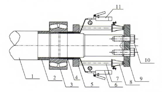
| Num | 1 | 2 | 3 | 4 | 5 | 6 | 7 | 8 | 9 | 10 | 11 |
|---|---|---|---|---|---|---|---|---|---|---|---|
| Part Name | Rotor Shaft | Setting Sleeve | Bearing | Withdrawal Sleeve | Pressure Plate | Inner Fuel Pump | Round Bar | Jack | Tie Plate | Bolt | Outter Fuel Pump |
Mounting Examples of Bearings
Bearing withdrawal sleeve has 2 types: one is with no oil hole; The other is with 2 oil holes in the end face of the discharge casing.
Bearing Installation Without Oil Hole Withdrawal Sleeve
On September 14, 2016, the bearing brush ring at the pulley end was found, and the bearing was replaced on hammer mill machine site. After it is extracted from the reservoir, the original clearance is measured as 0.5mm. Compare the data in Table 1. After the bearing is installed, the clearance should be controlled within 0.5-(0.17 ~ 0.32)mm= 0.33 ~ 0.18mm.
As it is the first time to install the bearing at the pulley end, it need to be done properly. After the bearing and the withdrawal sleeve are placed, pretighten the bearing by hitting the withdrawal sleeve with copper bar. As the shaft extension is too long and the installation space is limited, bearing pretighten is difficult to meet the requirements.
According to the actual situation on site, a special tool is produced to measure the distance of pulley end bearing to the shaft end diameter of axle sleeve position, which is processing a Φ 345 mm * Φ 365 mm * 850 mm casing pipe, use flange welding to seal the casing pipe at one end wall with steel plate of 20 mm thickness; Put the casing on the shaft, lift it with the old crusher hammer shaft, and beat the casing pipe.
The bearing clearance was measured through multiple impacts, and finally the bearing mounting clearance was controlled within 0.30mm.